Fuse
Before the advent of the circuit breaker, fuses were common in the home and office. A fuse serves one purpose-to fail-and thus cut the flow of power in the event of a current load that has exceeded the safe capacity of the system components to absorb. While fuses come in many shapes and sizes, a PC fuse is almost always a small, clear glass tube with metal caps on each end and a wire inside the tube to electrically connect the two caps (see Figure 13.10). In general, the thicker the wire, the more current it can conduct before failing. When a fuse fails, the wire will melt or be broken. You can check for a "blown" fuse by seeing if the wire is intact or broken. The amperage (A) rating (stamped on the metal cap) indicates the maximum current the wire is rated to conduct. Be sure not to exceed to the rated limits of the PC design for a fuse, because an excess power load can damage or destroy the system.
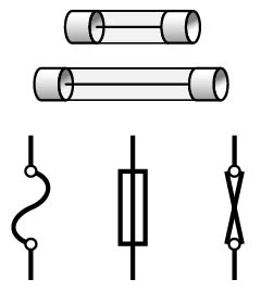
Figure 13.10 Fuses
If a fuse in a specific location fails more than once or repeatedly, the system is being overloaded, and you need to isolate the problem causing the failure. Fuses are often found on power supplies and many external components. If a fuse fails, try first replacing it with another of the same rating. If the replacement also fails, the fault probably lies with the motherboard or another internal part.
Capacitors
A capacitor is an electrical component used to hold an electrical charge. In photography, electronic flashes use capacitors to build up power before a picture is taken and to vary the amount of power used in a flash to control the exposure. In PCs, they are often used to regulate the flow of current to areas of the system circuits for a short period of time. Some are fixed-capacity models, whereas others can absorb or hold variable amounts of power. The amount of electrical current a capacitor can control is called capacitance, measured in microfarads (see Figure 13.11).
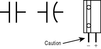
Figure 13.11 Capacitors
Most PC power supplies employ an electrolytic capacitor. These devices are able to retain a significant charge for long periods. You should work with such components only if you are properly trained to know how to release any residual charge before disconnecting, testing, removing, or replacing one. Failure to follow safe procedures can result in injury or death to you, and damage to the system. These capacitors have a distinct polarity (negative and positive) to their two leads.
CAUTION
Before you test a capacitor you must discharge the power supply. Failure to discharge can create a serious hazard to you and your equipment.
Rectifiers and Diodes
Rectifiers are devices that convert AC power into a DC form (rectification). A diode is a device that lets current flow in only one direction (see Figure 13.12). Two or more diodes connected to an AC supply will convert the AC voltage to DC voltage.
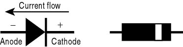
Figure 13.12 Diodes
Single diodes are generally used to convert AC current to pulsating DC current (see Figure 13.13). Two diodes working in parallel produce half-wave rectification, resulting in a pulsating direct current. Four diodes produce full-wave rectification, with a continuous stream of pulses.
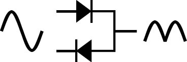
Figure 13.13 Half-wave rectifier
Normally, a computer technician does not test at this level; however, diodes can be tested with a multimeter. With the power turned off, test for resistance across both leads of the diode. Then reverse the leads of the multimeter and test again. A good diode will exhibit low resistance in one direction and high resistance in the other.
Transistors
The invention of the compact, power-efficient, and reliable transistor created the modern electronics industry; replacing bulky, power-hungry, and temperamental vacuum tubes. Transistors are basically a pair of diodes connected in series with an "on-off" switch (see Figure 13.14). Varying the voltage sent to a transistor turns the switch on or off. Early computers used vacuum tubes as switches and were so large that technicians could actually step inside the larger ones to plug in or remove the tubes in order to program them.
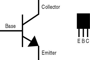
Figure 13.14 Transistors
Transistors can be tested; however, this often requires special equipment. Due to the reliability of transistors, a computer technician normally does not need to do this level of testing.
Transformers
The most common forms of electrical transformers are step-down or step-up devices. A step-down transformer decreases the transformer's voltage on the output side; a step-up model increases it. Both have a primary wire coil connected to other coils-secondary coils-joining two or more AC circuits.
Electronic transformers generally contain stacks of thin metal-alloy sheets, known as laminations, with coils of copper wire wound around them. They are commonly employed in a circuit along with a rectifier which, as we have seen, supplies DC power to the equipment. In the PC power supply, the transformer's secondary coils are used to provide 12-volt, 5-volt, and 3.3-volt outputs used by various components (see Figure 13.15).
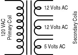
Figure 13.15 Transformer
Testing a Transformer
As noted, a transformer is made up of several coils of wire. Because each coil in the transformer is continuous, each can also be tested for continuity. Follow these steps:
- Disconnect the power.
- Discharge all capacitors.
- Check the bottom of the circuit board of the power supply to be sure all leads have been disconnected. The primary connections, as well as the secondary connections, can be located below the transformer.
- Configure the multimeter to measure continuity (or resistance).
- Simultaneously touch each lead of a multimeter to one of the pairs of contacts.
A good transformer will show a reading of low resistance. A very high reading could indicate that one of the coils is broken.
Inductors (Coils)
Inductors, commonly called coils because of their shape, are loops of conductive wire (see Figure 13.16). Current passing through the inductor sets up a magnetic field. This field reduces any rapid change in current intensity. Inductors can also be used to distinguish between rapidly and slowly changing signals in a circuit.
![]()
Figure 13.16 Coil
Testing a Coil
Since an inductor is simply a wire coil, it can be tested for continuity in much the same way as a transformer is tested.
Visually inspect the wire for deterioration. If it shows signs of breakage or burned areas, it should be replaced. If the wire looks good, follow up with a conductivity test. Turn the system power off. Disconnect one lead to the coil (this might require a soldering iron) and connect one meter lead to each end of the coil. A null or low reading indicates continuity. A reading of high or infinite resistance indicates a lack of continuity. Replace the coil.