Address Bus
The word "location" is italicized in the last paragraph to underscore the importance of location in PC memory operations. The content of RAM is changing all the time, as programs and the computer itself use portions of it to note, calculate, and hold results of actions. It is essential for the system to know what memory is assigned to which task and when that memory is free for a new use. To do so, the system has to have a way to address segments of memory and to quickly change the holdings in that position. The portion of the PC that does this is the address bus.
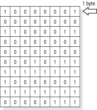
Think of the address bus as a large, virtual table in which the columns are individual bits (like letters) and each row contains a string of bits (making up a word). The actual lengths of these words will vary depending on the number of bits the address bus can handle in a single pass. Figure 4.6 shows a table containing 1s and 0s. Each segment is given an address, just like the one that identifies a home or post office box. The system uses this address to send data to or retrieve data from memory.

Figure 4.6 Memory spreadsheet
Like all the other buses in a PC, this one is a collection of conductors. It links the physical memory to the system and moves signals as memory is used. The number of conductors in the address bus determines the maximum amount of memory that can be used (memory that is addressable) by the CPU. Remember that computers count in binary notation. Each binary digit-in this case, a conductor-that is added to the left will double the number of possible combinations.
Early data buses used eight conductors and, therefore, 256 (28) combinations of code where possible. The maximum number of patterns a system can generate determines how much RAM the data bus can address. The 8088 used 20 address conductors and could address up to 1,048,576 bytes of memory locations, or 220. Today's PCs can address a lot more than that, and, in many cases, the actual limiting factor is not the number of patterns, but the capacity of the motherboard to socket memory chips. In all cases, the total amount of memory is the factor of 2X, where X = the number of connectors.
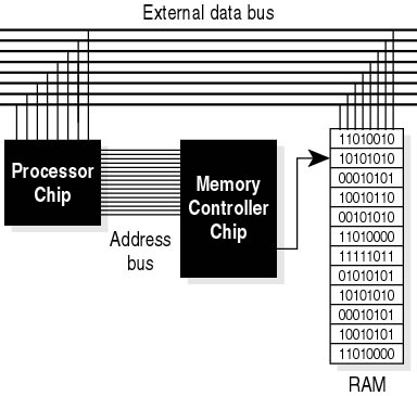
The CPU does not directly connect to the memory bus, but sends requests and obtains results using the system's memory controller. This circuitry acts as both postmaster and translator, providing the proper strings of data in the right order, at the right time, and in a form the CPU can use. As mentioned before, any write or read action will require at least two clock cycles to execute. (It can require more clock cycles on systems that do not have memory tuned to the maximum system clock speed. In that case, the PC will have to use additional clock cycles while it waits for the memory to be ready for the next part of the operation.)
Figure 4.7 shows a diagram of the process with the CPU and RAM stack on the external data bus. The address bus is connected to the memory controller. It fetches and places data in memory.

Figure 4.7 CPU and RAM