Today's floppy disks (see Figure 8.1) are made of flexible plastic and coated with a magnetic material. To protect the disk from dust and physical damage, it is packaged in a plastic or coated paper case. The main reason for the popularity of floppy disk drives and disks is that they provide inexpensive read/write (R/W) removable media. The data stored on a floppy disk can be moved from one computer to another, provided both have the same type of drive. In general, it is a good idea to protect your data by always keeping two copies of any data file that you create (the original and a backup), and the floppy disk is an excellent medium for backing up, storing, or distributing copies of relatively small files, such as word-processing documents.
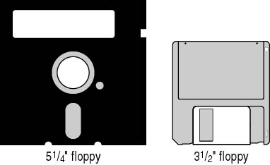
Figure 8.1 Floppy disks
The following table describes various floppy disks and their capacities.
| Disk Size | Capacity | Description |
|---|---|---|
| 5.25-inch | 160 KB | Single-sided single-density-the first model. |
| 5.25-inch | 360 KB | Double-sided single-density. |
| 5.25-inch | 720 KB | Double-sided double-density. |
| 5.25-inch | 1.2 MB | Double-sided high-density. |
| 3.5-inch | 720 KB | Double-sided double-density. |
| 3.5-inch | 1.44 MB | Double-sided high-density-today's standard. |
| 3.5-inch | 2.88 MB | Double-sided quad-density. This format has never really gained in market share and is not common on today's PCs. |
The only major differences between the 5.25-inch and the 3.5-inch disk drives (other than physical size) are that the 5.25-inch drive has a slot connector and the 3.5-inch drive has a pin connector for engaging and spinning the disk, and they use different power plugs and voltages.
All floppy disk drives are connected to the motherboard's external data bus by a 34-conductor ribbon cable, shown in Figure 8.2. This cable has a seven-wire twist in lines 10 through 16. This ensures that when two floppy disk drives are attached, the drive-select and motor-enable signals on those wires can be inverted to "select" which drive becomes the active target. The other wires carry data and ground signals. The connector end of the cable with the twist always goes toward the drives.
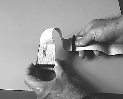
Figure 8.2 Floppy disk drive cable with a twist
Early BIOS was developed to recognize one or two floppy disk drives. No more than one 34-pin cable for floppy disk drives can be installed in a single system without resorting to special hardware. When a floppy disk drive is installed on the end connector (near the twist), the drive is logically designated as the A drive by BIOS. The drive attached in the middle of the cable is always the B drive. The BIOS will not recognize a B drive unless an A drive is physically installed.
The number 1 red wire must be connected to the number 1 pin on the drive. If this is not correctly installed, the drive will not work (although no damage can be done by installing the connector backward).
NOTE
If you install a new drive and notice that the indicator light comes on and stays on, the cable is most likely backward.
The power connection for a floppy disk drive, shown in Figure 8.3, is either the large Molex type connector on the 5.25-inch drive (see Tutorial 5, Lesson 1: Power Supplies for details) or the smaller mini connector, on the 3.5-inch drive. A large number of power supplies, designed primarily for tower systems, provide a special connector exclusively for 3.5-inch floppy disk drives. This connector is a two-strand connection that provides a 5-volt power connection to the 3.5-inch drive.
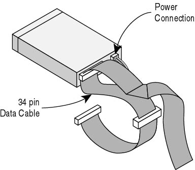
Figure 8.3 Floppy disk drive cable connections
After you physically install a floppy disk drive, you need only set the proper CMOS settings for the type and position (first or second) and the installation will be complete. In CMOS setup, select the drive (A or B) and enter the correct capacity. (CMOS stands for complementary metal-oxide semiconductor.)
NOTE
Many older CMOS chips won't have settings for 1.44 MB or 2.88 MB 3.5-inch floppy disk drives because they were developed before these drives were introduced. Also, the 5.25-inch drives are virtually obsolete, and the CMOS of the future might not have settings for them. Several third-party utilities will allow the CMOS to accept the necessary values to support these drives.