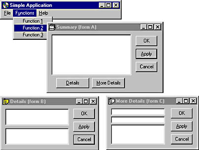
Figure 13-5 A deceptively simple-looking application
The application has been designed so that only form A's OK or Apply button commits data to the database. Each form has a buffer in which it holds edits to its own subset of the data, and the contents of these buffers are shuffled around as the OK, Apply, and Cancel buttons are manipulated on forms B and C. Figure 13-6 shows the state transitions for this GUI, and Figure 13-7 is a close-up view of two states, showing the actions the application will take on each transition.
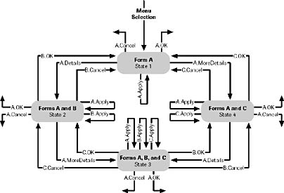
Figure 13-6 FSM for the application shown in Figure 13-5
Close examination of Figures 13-6 and 13-7 reveals some omissions. There are 11 events, but not all states have 11 arrows leaving them. This is partly because not all events can occur in all states. For example, it isn't possible to click form C's Apply button in state 1. But some events, such as the Details button events in states 2 and 3, are omitted because there just isn't enough space for them. Leaving out events like this undermines a basic reason for using an FSM, which is to verify that you've considered all state/event combinations. This is where the tabular form is a much better representation-it's easier to draw, and it clearly shows all state/event combinations. The two notations complement each other: in practice the state diagram is a useful sketch that conveys the feel of the GUI, while the tables provide a basis for implementation.
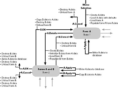
Figure 13-7 Close-up view of a fragment of Figure 13-6