We are going to model four links, and four cylinder bars (we can think of them as joints) to connect the links. We'll make circular holes in each link at both ends so that they can be assembled in the end. The length between the two holes of the link would considered actual link length.
Some basic points that can be helpful in Creo.
- Use mouse wheel to zoom in or out.
- Hold Middle Mouse Button and move the mouse to orbit.
- Hold Middle Mouse Button and hold Shift key to pan.
Modeling the ground link
Open Creo parametric, click in New in left top corner and choose part and uncheck the “Use default template”. If we do not uncheck it, the measurement units would be in inches.
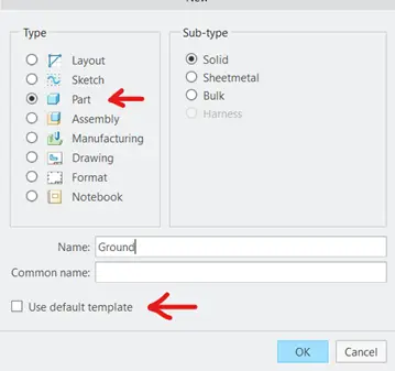
Click “OK”.
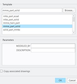
Now select “mmns_part_solid”, by doing so, all of the measurements would be taken in millimeters.
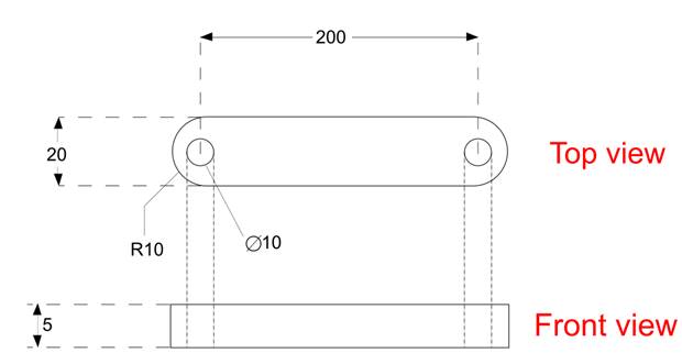
We would be using the above drawing for the dimensions of the ground linkage.
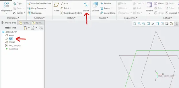
Click on “Top” plane from the model tree on the left and then click on the sketch from the top. By selecting top plane, we are sketching the top view.
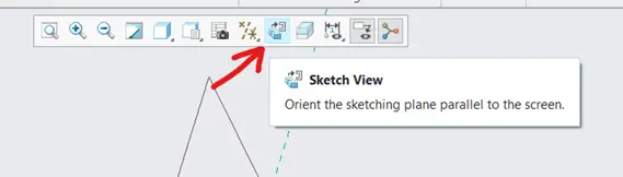
After entering the sketch mode, click sketch view from above to orient the sketching plane parallel to the screen.
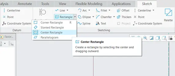
From the sketching tab, click the center Rectangle. The Center Rectangle draws symmetrical rectangle from its center to the four sides. Click on the origin of the screen and draw the rectangle. Left click to draw the rectangle and Middle mouse button to let go.
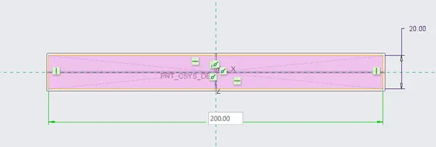
Change the dimensions of the rectangle, double click on the dimensions to change them.
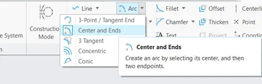
Select the center and ends arc to draw the circular ends of the rod.
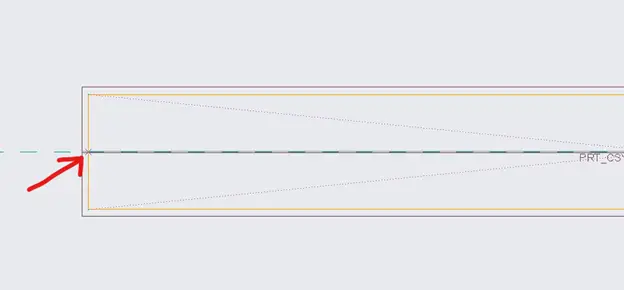
Click on the end of rectangle of x axis to set that point as a center of the arc. Now click on the corners of the rectangle to complete the arc.
Now our geometry would look as shown in the above figure.
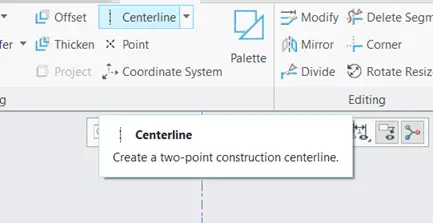
Click on the Centerline from the sketch tab, and draw a vertical centerline as shown above. To mirror the sketch we need a centerline.
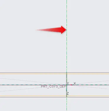
The centerline drawn is shown above. And after that we are going to mirror the arc.
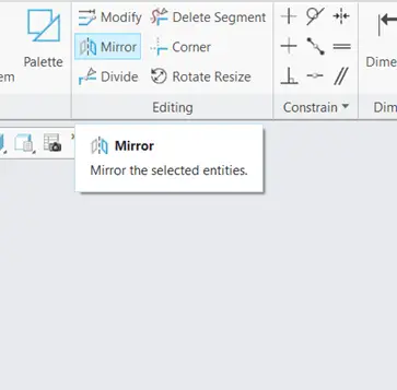
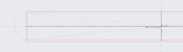
Select the drawn arc by pressing Left Mouse Button and then click on the mirror function in sketch tab and after that click on the centerline that we just drew to mirror the arc on the other side of the sketch.
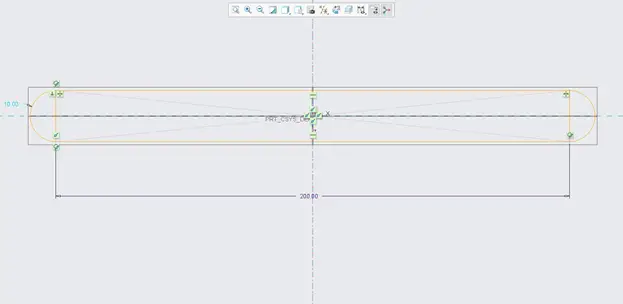
Now our geometry would look like the geometry shown in the above figure. We are going to delete the unnecessary segments of the geometry.
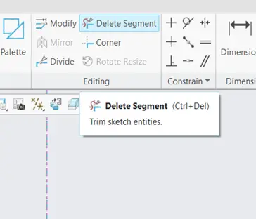
Click on delete segment tool as shown in the figure above.
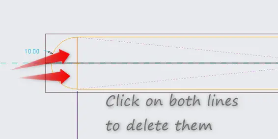
Delete the unnecessary segments as shown above from both sides. We have done this part so that we can have a closed geometry. It is important to remember that it is necessary to make a closed geometry in Creo.
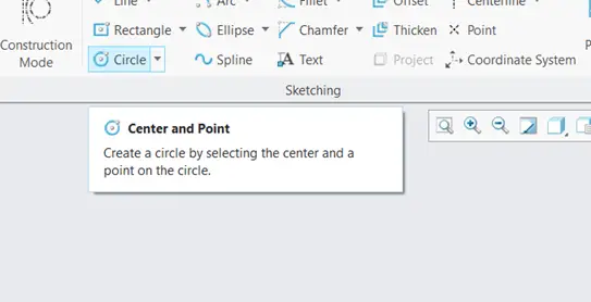
Now, we are going to draw a circle to make a hole in our geometry. Select the circle from Sketch tab as shown above.
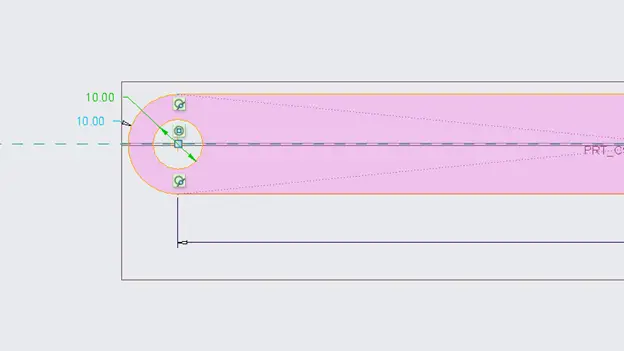
Draw the circle on the center of the arc and its diameter should be 10 mm. And then mirror the circle to the other side.
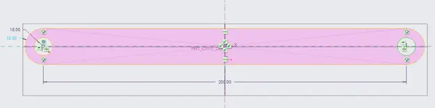
Click on the Middle Mouse Button to let go. Our sketch should look like this.
Click on the “OK” button to confirm the sketch.
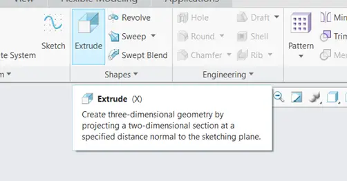
Now click on the sketch from the model tree and then click extrude to apply extrude command on the sketch.
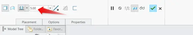
Choose the value of extrude to be 5 mm. As we can see that the model is now In 3d form. Click on the green tick button to confirm.
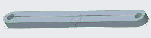
Now our model should look like as shown above.