Go to File > Save > Save a copy and name the file “Crank”.
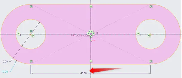
We just have to change the length that is shown above. We have discussed
Modeling the Rocker
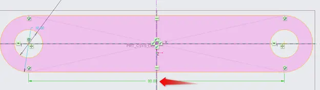
The procedure for modeling the rocker is same as that of ground. Just change the length to “90 mm”. Go to File > Save > Save a copy and name the file “Rocker”.
Modeling the Coupler
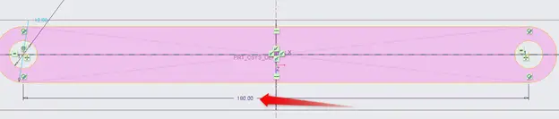
The procedure for modeling the rocker is same as that of ground. Just change the length to “180 mm”. Go to File > Save > Save a copy and name the file “Coupler”.
Modeling the joint
We are going to model the joint. The joint is used to assemble all the links together.
- Diameter = 10 mm.
- Length = 10 mm.
Create a new part file in Creo parametric and name it joint. Now click on the top view and then click sketch.
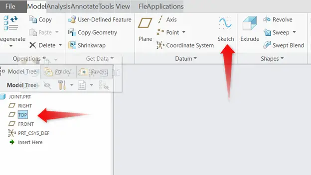
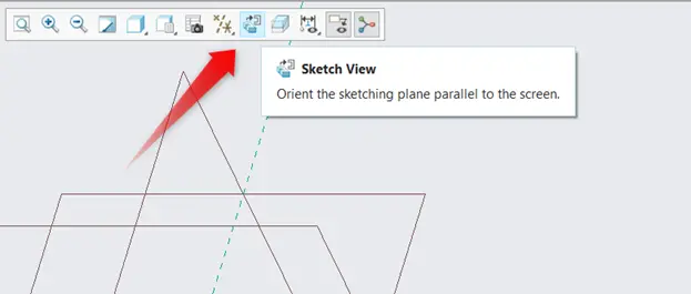
After that, click on the sketch view to orient the sketching plane parallel to the screen.
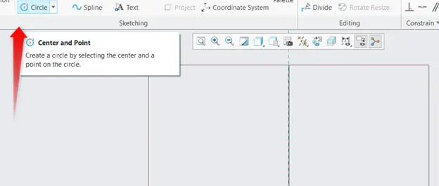
Now click on the circle and select. Click on the origin to draw the circle and its diameter should be 10 mm.
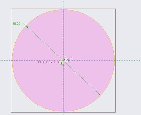
Click on Tick to confirm the sketch.
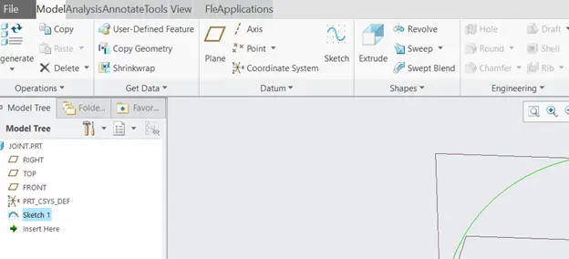
Now click on sketch 1, and then click on extrude command to extrude the sketch.
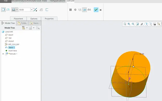
The length that the sketch is to be extruded is “10 mm”, and then click tick to confirm.